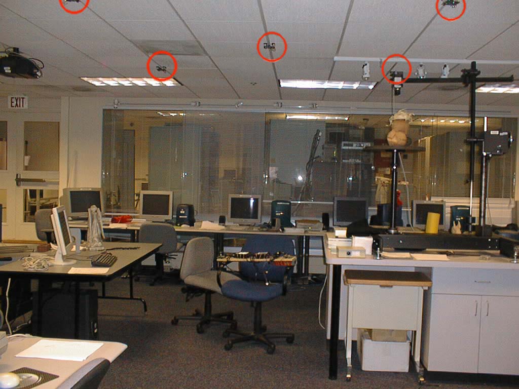
 Lab Setup
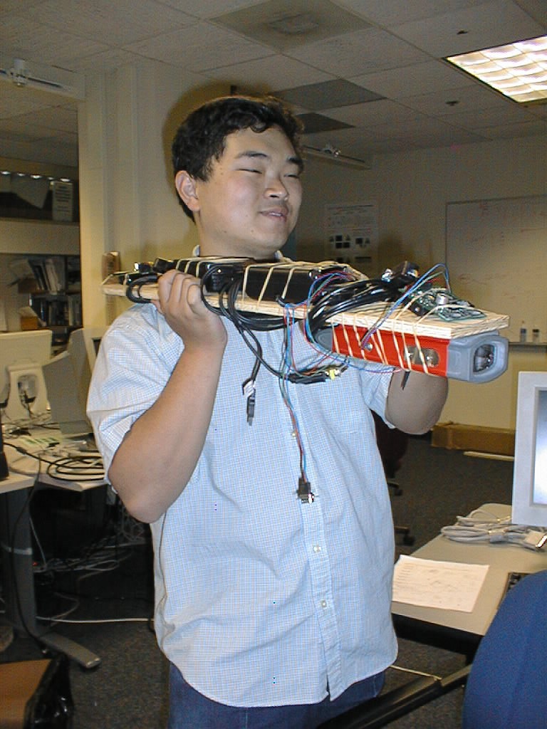
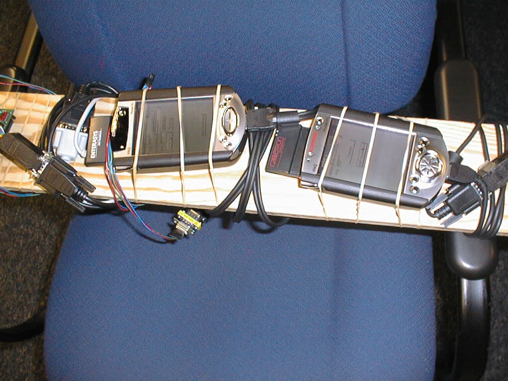
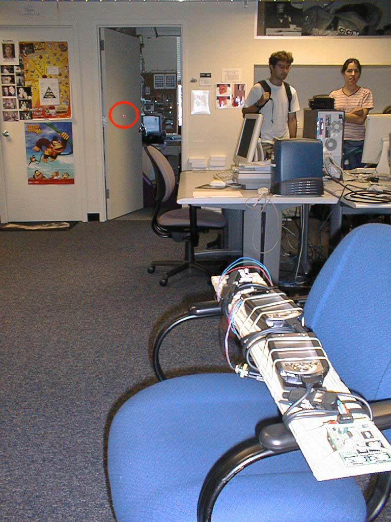
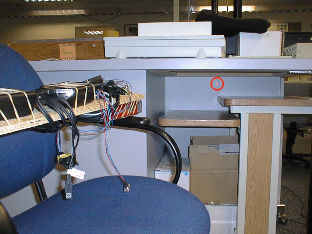
To create a pointing device, we require a ray in space;
therefore, we need a point and a vector.
To accomplish this, we need two cricket listeners,
one to give us a point in space and the other
to give position. We can also use a gyroscope. To get an
accurate distance (direction and
distance would give us the vector), we use a laser rangefinder
(Disto Memo by Leica Geosystems).
It has the added advantage of being able to see the dot on
the target as well as get a continuous reading.
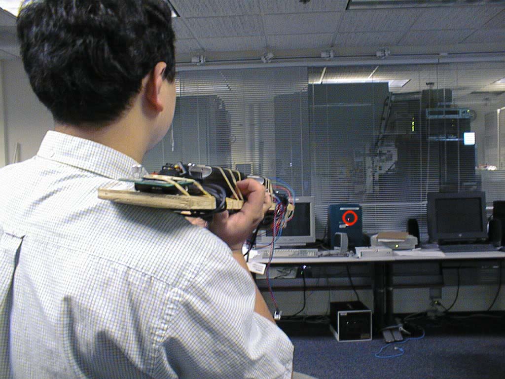
The term Software Flashlight comes from the fact
that once you have the coordinates of a
point on the wall, you can project onto the wall information
about the structure.
For example, we can retrieve wiring information about
a certain surface from a database given
its coordinates and actually projecting the diagram
onto the surface itself, effectively
giving you "X-Ray Vision." One can use this technology
for a variety of other purposes.
One can project geometric information that does not yet
exist; for example, one can project
onto a wall the location of an electrical socket to be
installed so that the electrician
who comes to install it does not have to measure, or
at least, get a good general idea
of where it should go.

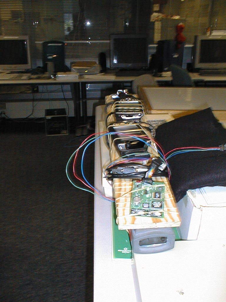
 Closeup
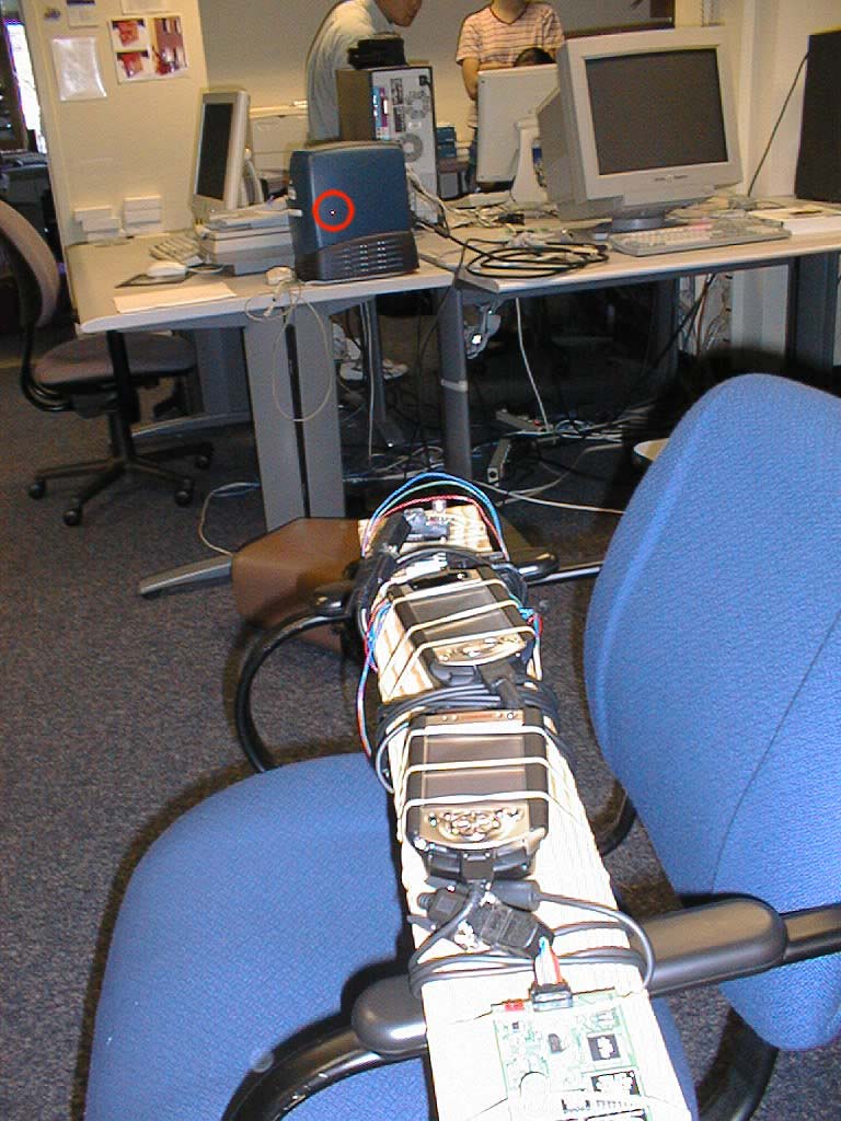
The workstation which runs Cricket3DServer actually
does all the computation. It
processes the signal to smooth out the noise, calculates
the positions of the listeners,
gets a reading from the laser and plots them in 3D. To calculate
position, one missing
piece of information is the location of the beacons themselves.
They can be manually
Entered in the coordinate system of the building model, but once
you have enough to
calculate position, the device itself can be used to enter the
coordinates of nearby beacons.
The model file itself is in the easily readable UniGrafix format
and beacon information is
stored in an easily human-readable file format as well.
MIT Building NE43 2nd Floor UniGrafix File
Sample Beacon Location File


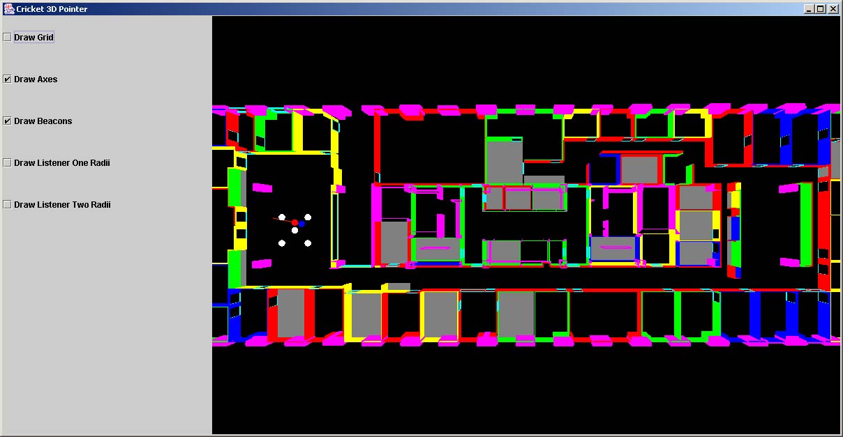

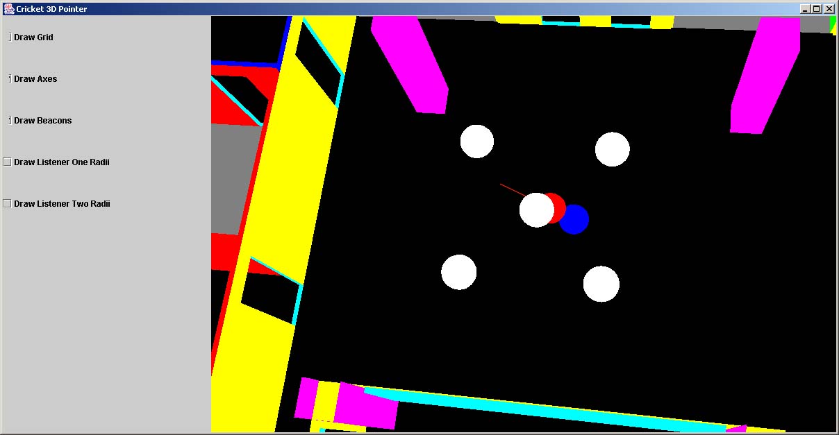
The visualization has a primitive first-person type walkthrough
interface. It can render a grid of a certain
spacing - useful for buildings where there is a nice coordinate
system defined by physical landmarks
and also for walking a small cursor through to enter beacon
coordinates manually.
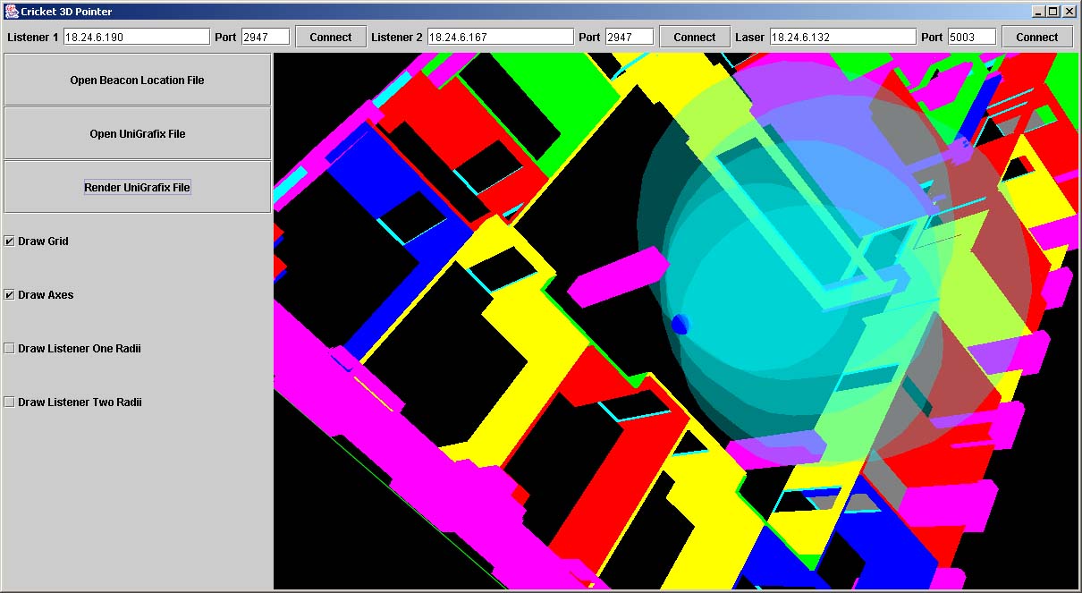
The visualization can also render spheres that represent the
distance received from each beacon.
Where they intersect is the location of the listener.
Screenshot (old interface):
All of this is an intermediate step in building a software
flashlight. With some additional refinements
to position calculations, the device can be used to start
populating the environment.
Mesa3D's implementation of
OpenGL has been successfully compiled onto the iPAQ running Familiar Linux.
Compilation Instructions for Mesa3D + GLUT + your own programs
We recently got the HP F1252A PCMCIA VGA-Out card
to work with Familiar linux on the iPAQ.
OpenGL runs on it with an acceptable level of
performance considering how the iPAQ has
no FPU. Screenshots will be up soon.
Wireframes (possibly textures) can be downloaded from the model
database and projected onto the wall.
Theoretically, anything can be projected, so one can put onto the wall
geometry that does not yet exist.